
The Steel Joints add-on provides you with the option to connect circular hollow sections using welds.
It is possible to connect the circular sections to each other or to planar structural components. The fillets of standard and thin-walled sections can also be connected with a weld.
Go to Explanatory Video
In the Steel Joint add-on, you can design the connections of members with composite cross-sections. Furthermore, you can perform joint design checks for almost all thin-walled cross-sections in the RFEM library.
Go to Explanatory Video
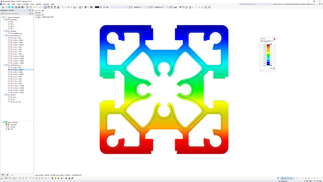
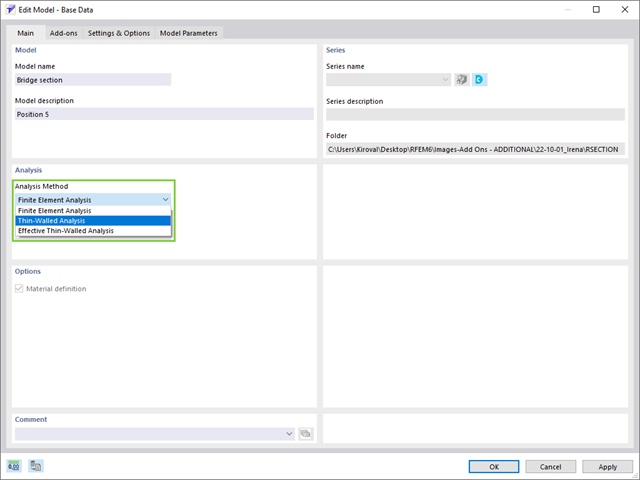
Do you already know about RSECTION 1? The stand-alone program RSECTION helps you to determine the section properties for any thin-walled and massive cross-sections. Then, it performs a stress analysis. RSECTION combines the programs SHAPE‑THIN and SHAPE‑MASSIVE. Compared to these programs, we have added the following new features in RSECTION:
- Graphical display of stress components
- Scripting using Javascript

Compared to the RF-/STEEL Warping Torsion add-on module (RFEM 5 / RSTAB 8), the following new features have been added to the Torsional Warping (7 DOF) add-on for RFEM 6 / RSTAB 9:
- Complete integration into the environment of RFEM 6 and RSTAB 9
- 7th degree of freedom is directly taken into account in the calculation of members in RFEM/RSTAB on the entire system
- No more need to define support conditions or spring stiffnesses for calculation on the simplified equivalent system
- Combination with other add-ons is possible, for example for the calculation of critical loads for torsional buckling and lateral-torsional buckling with stability analysis
- No restriction to thin-walled steel sections (it is also possible to calculate ideal overturning moments for beams with massive timber sections, for example)
- Available for general thin-walled RSECTION cross-sections
- Classification according to
- EN 1993-1-1
- EN 1993-1-4
- EN 1999-1-1
- Determination of the effective section according to
- EN 1993-1-5
- EN 1993-1-3
- EN 1999-1-1
- Consideration of the effects of distortional buckling of cold-formed sections via eigenvalue method
- Determination of the stresses on the effective section and gross section
- Cross-section, stability, and serviceability limit state design checks of RSECTION cross-sections of Class 4 according to EN 1993‑1‑1 or EN 1999‑1‑1 in the Steel Design or Aluminum Design add-ons
- Cross-section checks for cold-formed RSECTION cross-sections according to EN 1993‑1‑3 in the Steel Design add-on
- Available for all National Annexes integrated in the Steel Design add-on
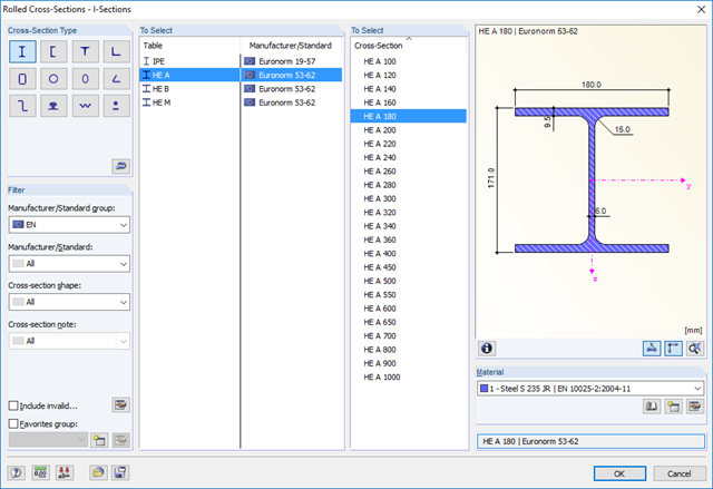
- Extensive library of rolled, parametric thin-walled and thick-walled cross-sections
- Extensible library for material properties
- Import of dxf files
- Cross-section properties of thin-walled or thick-walled cross-sections
- Ideal section properties of cross-sections consisting of different materials
- Stress analysis
- Plastic capacity design with interaction of internal forces according to the Simplex Method
- Design of reinforcement and the subsequent design of concrete cross-section in the Concrete Design add-on (see Product Feature)
- Saving cross-sections as a block
- Scripting with JavaScript
- Interface with MS Excel for exporting tables
- Connection to Webservice & API (for example, optional creation of cross-section and access to result tables)
- Printout report
RSECTION contains an extensive library of rolled sections, as well as parametric thin-walled and massive cross-sections. You can compose them or supplement them with new elements.
Graphical tools and functions allow you to model complex section shapes in the usual way common for CAD programs. The graphical input supports, among other things, the setting of arcs, circles, ellipses, parabolas, and NURBS. As an alternative, you can import a DXF file and use this as the basis for further modeling. You can easily model a section consisting of different materials with minimum effort.
Furthermore, a parameterized input allows you to enter the cross-section dimensions and internal forces in such a way that they depend on certain variables.
You can also carry out all inputs by means of a script.
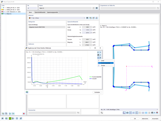
You can perform the calculation of the warping torsion on the entire system. Thus, you consider the additional 7th degree of freedom in the member calculation. The stiffnesses of the connected structural elements are automatically taken into account. It means, you don't need to define equivalent spring stiffnesses or support conditions for a detached system.
You can then use the internal forces from the calculation with warping torsion in the add-ons for the design. Consider the warping bimoment and the secondary torsional moment, depending on the material and the selected standard. A typical application is the stability analysis according to the second-order theory with imperfections in steel structures.
Did you know that The application is not limited to thin-walled steel cross-sections. Thus, it is possible for you, for example, to perform the calculation of the ideal overturning moment of beams with solid timber cross-sections.

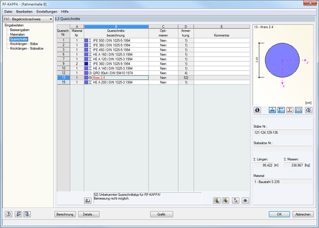
- Cross-section optimization
- Transfer of optimized sections to RFEM/RSTAB
- Design of any thin-walled section from RSECTION
- Representation of a stress diagram on a section
- Determination of normal, shear, and equivalent stresses
- Output of stress components for the individual member internal force types
- Detailed representation of stresses in all stress points
- Determination of the largest Δσ for each stress point (for example, for fatigue design)
- Colored display of stresses and design ratios for a quick overview of the critical or oversized zones
- Output of parts lists
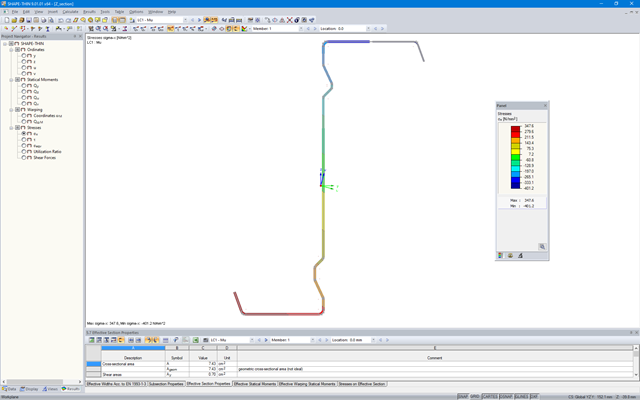
SHAPE‑THIN determines the effective cross-sections according to EN 1993‑1‑3 and EN 1993‑1‑5 for cold-formed sections. You can optionally check the geometric conditions for the applicability of the standard specified in EN 1993‑1‑3, Section 5.2.
The effects of local plate buckling are considered according to the method of reduced widths, and the possible buckling of stiffeners (instability) is considered for stiffened sections according to EN 1993‑1‑3, Section 5.5.
As an option, you can perform an iterative calculation to optimize the effective cross-section.
You can display the effective cross-sections graphically.
Read more about designing cold-formed sections with SHAPE-THIN and RF-/STEEL Cold-Formed Sections in the technical article "Design of Thin-Walled, Cold-Formed C-Section According to EN 1993‑1‑3".
Design of Thin-Walled, Cold-Formed C-Section According to EN 1993-1-3 More about RF-/STEEL Cold-Formed Sections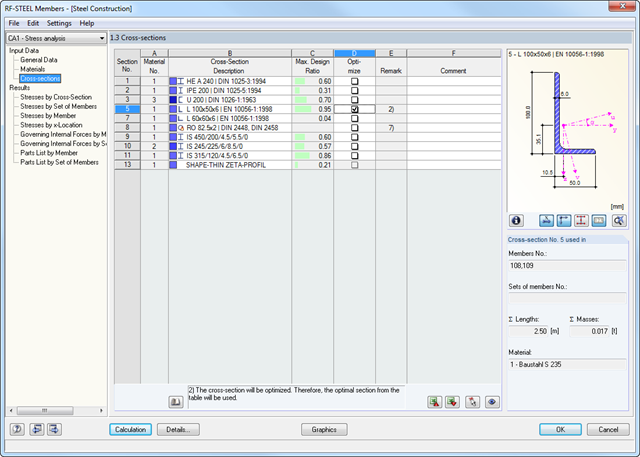
- Cross-section optimization
- Transfer of optimized sections to RFEM/RSTAB
- Design of any thin-walled cross-section from SHAPE-THIN
- Representation of a stress diagram on a section
- Determination of normal, shear, and equivalent stresses
- Stress results of individual internal forces types
- Detailed representation of stresses in all stress points
- Determination of the largest Δσ for each stress point (for example, for fatigue design)
- Colored display of stresses and design ratios for a quick overview of the critical or oversized zones
- Parts lists and quantity surveying
RF-/STEEL EC3 automatically imports the cross-sections defined in RFEM/RSTAB. It is possible to design all thin-walled cross-sections. The program automatically selects the most efficient method according to standards.
The ultimate limit state design takes into account several loads and you can select the interaction designs available in the standard.
The classification of designed cross-sections into Classes 1 to 4 is an essential part of the analysis according to Eurocode 3. This way, you can check the limitation of the design and rotational capacity by means of the local buckling of cross-section parts. RF-/STEEL EC3 determines the c/t-ratios of the cross-section parts subjected to compression stress and performs the classification automatically.
For the stability analysis, you can specify for each member or set of members whether flexural buckling occurs in the y- and/or the z-direction. You can also define additional lateral restraints in order to represent the model close to reality. The slenderness ratio and elastic critical load are determined automatically on the basis of the boundary conditions of RF-/STEEL EC3. The elastic critical moment for lateral-torsional buckling required for the lateral-torsional buckling analysis can be determined automatically or specified manually. The load application point of transverse loads, which has an influence on the torsional resistance, can also be taken into account via the setting in the details. In addition, you can take into account rotational restraints (for example trapezoidal sheeting and purlins) and shear panels (for example trapeziodal sheeting and bracing).
In modern construction, where cross-sections are increasingly slender, the serviceability limit state is an important factor in structural analysis. RF-/STEEL EC3 assigns load cases, load combinations, and result combinations to different design situations. The respective limit deformations are preset in the National Annex and can be adjusted, if necessary. In addition, it is possible to define reference lengths and precambers for the design.
- Full integration in RFEM/RSTAB including import of all relevant internal forces
- Intelligent presetting of flexural buckling-specific design parameters
- Automatic determination of the distribution of internal forces and classification according to DIN 18800, Part 2
- Optional import of buckling lengths from the RF-STABILITY/RSBUCK add-on module. For this, a comfortable graphical selection of the relevant buckling mode is possible
- Optimizing Cross-Sections
- Optional calculation according to both design methods of DIN 18800, Part 2
- Automatic determination of the most unfavorable design location, also for tapered members
- Check of c/t-limit values according to DIN 18800, Part 1
- Design of any thin-walled RFEM/RSTAB or SHAPE-THIN section for compression and bending without interaction according to the elastic-plastic method
- Design of I-shaped rolled and welded sections, I-like sections, box sections, and pipes subjected to bending and compression with iteration according to the elastic-plastic method
- Clearly arranged, comprehensible design checks with all intermediate values in the short and long forms
- Parts list of members and sets of members
- Direct export of all results to MS Excel
- A manual with manually calculated examples